Answer:
light doesn't need a medium through which to travel because the speed of light is experimentally constant
The decimal point is placed after two digits starting from the end. For each decimal place, we can write the number divided by 100.
21.12 can be written as  .
.
Divide the numerator and denominator by 2:

The numerator and denominator can be divided by 2 again:

There is no other common factor between numerator and denominator other than 1. Hence, it is the reduced form.
Answer:
1.28 m
Explanation:
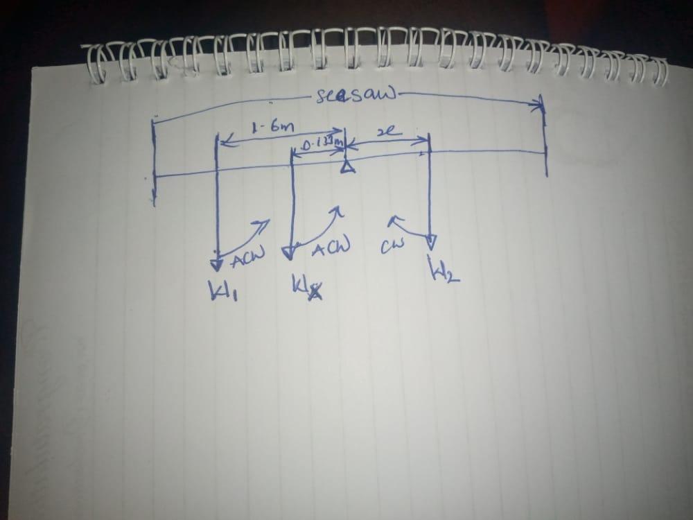
As shown in the diagram attached,
According to the principle of moment,
For a body at equilibrium,
Sum of clockwise moment = sum of anticlockwise moment.
Taking moment about the pivot,
W₁(1.6)+W(0.133) = W₂(x)............... Equation 1
Where W₁ = Weight of the first child, Wₓ = Weight of the seesaw, W₂ = weight of the second child, x = distance of the second child from the pivot.
But,
W = mg
Where g = 9.8 m/s², m = mass of the body
Therefore,
W₁ = 26×9.8 = 254.8 N,
Wₓ = 18×9.8 = 176.4 N
W₂ = 34.4×9.8 = 337.12 N
Substitute these values into equation 1
(254.8×1.6)+(176.4×0.133) = 337.12(x)
407.68+23.4612 = 337.12x
337.12x = 431.1412
x = 431.1412/337.12
x = 1.2789
x ≈ 1.28 m
2.72 N
Explanation:
Step 1:
From the basic formula in electrostatics
F = E * q
where F = Force due to charges
E = Electric field strength
q = Charge
Step 2:
From the given question
q= 
E = 
F =  N
N
A) reactants interact to form products with different chemical and physical properties